INSTRUCTION BOARD FOR CHARGING SYSTEM
INSTRUCTION BOARD FOR CHARGING SYSTEM Specification
- Assembly
- Pre-assembled
- Power Type
- Non-electric
- Use
- Instructional Guidance for Charging System
- Weight
- Approx. 400 grams
- Model No
- CS-IB-11
- Features
- Weatherproof, Easy to Mount, Fade-proof
- Style
- Printed Board
- Size
- Standard
- Surface Finish
- Glossy Laminated
- Type
- Instruction Board
- Material
- Rigid PVC
- Dimensions
- 30 x 45 cm
- Shape
- Rectangular
- Color
- Multicolor (White Base with Multicolored Print)
- Function
- Display Charging Instructions
- Age
- All Age Groups
- Advantage
- Clear, Durable and Water Resistant
- Suitable Environment
- Indoor and Outdoor
- Maintenance
- Wipe Clean with Damp Cloth
- Application Area
- EV Charging Stations, Parking Lots, Workshops
- Language
- English
- Mounting Type
- Wall Mounted (Provision for Hanging Holes)
- Compliance
- RoHS and IS Standard Conforming
- Print Type
- High Resolution UV Print
INSTRUCTION BOARD FOR CHARGING SYSTEM Trade Information
- Minimum Order Quantity
- 1 Unit
- Payment Terms
- Western Union, Paypal, Telegraphic Transfer (T/T), Cheque
- Supply Ability
- 100 Units Per Week
- Delivery Time
- 1 Week
- Main Export Market(s)
- Australia, North America, Eastern Europe, Western Europe, Africa, Central America, Middle East, South America, Asia
- Main Domestic Market
- All India
About INSTRUCTION BOARD FOR CHARGING SYSTEM
INSTRUCTION BOARD FOR CHARGING SYSTEM.
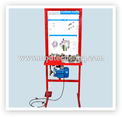
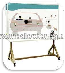
The Instruction board adopts the real components of charging system to illustrate charging system structure and working principle. The components are rigged onto colour circuit diagram. And made functional.
Features
Real and operatable Charging system such as alternator, meters etc is assembled onto a colour printed board to illustrating the structure and working process .
The alternator will be coupled electric motor, and the necessary electrical circuitry will be provided along with warning lamp, ignition switch, voltage meters etc., to demonstrate the working of charging system.
And exploded view arrangement of an alternator assembly will be displayed on the board.
Coloured circuit diagram on the training Module printed on to 6mm organic glass base. Where in the students can compare the diagram and actual diagram.
Detection terminals for operator to detect various sensors, actuators, electrical signals for engine control unit, such as resistive, voltage, current , frequency and wave form signals are provided on to the printed circuit diagram.
Fault setting switch bank will be provided to induce faults in the training module to demonstrate the fault and to diagnose faults.
Set the line break, grounding short circuit, improper contact or open circuit faults can be induced, user can adjust the number and type of faults.
The training module is fabricated using steel pipe frame with spray painted for good looks and the entire setup is provided with caster wheels with brakes for easy movement OF THE SAME .
High-Clarity Charging Instructions
The CS-IB-11 Instruction Board delivers step-by-step guidance for charging system use. With its large-scale multicolor print and clear layout, users can instantly grasp essential procedures. Whether in busy parking lots or dedicated EV charging stations, this board enhances safety and convenient access to instructions, reducing errors and confusion.
Exceptional Durability for Any Environment
Constructed from rigid PVC and featuring a glossy laminated surface, the board is built to withstand both indoor and outdoor conditions. Its weatherproof, fade-proof, and water-resistant qualities guarantee long-term performance, making it suitable for high-traffic areas. Routine cleaning requires only a damp cloth, ensuring lasting visibility.
FAQs of INSTRUCTION BOARD FOR CHARGING SYSTEM:
Q: How is the instruction board installed at EV charging stations or parking lots?
A: The board is designed with mounting holes that allow for easy wall installation. Simply use suitable fasteners or hooks to hang the board in a visible location, ensuring quick access to charging instructions.Q: What type of print is used to ensure the board remains visible over time?
A: High-resolution UV printing is used on a white base with multicolored print, which delivers sharp, vibrant graphics that remain fade-proof and durable even in challenging environmental conditions.Q: When should maintenance be performed on the instruction board?
A: Routine cleaning is recommended as needed, especially in outdoor or high-traffic locations. Wipe the glossy laminated surface gently with a damp cloth to remove dust, dirt, or debris, keeping instructions clear and legible.Q: Where can this instruction board be effectively used?
A: It is suitable for EV charging stations, parking lots, workshops, and other environments where clear charging system guidance is required. Its weatherproof design makes it reliable for both indoor and outdoor deployment.Q: What is the process for displaying instructional guidance using the board?
A: Once mounted, the board serves as a permanent reference, visually guiding users through charging procedures. The high-quality print layout ensures step-by-step instructions are easy to follow, improving operational safety and efficiency.Q: What benefits does the CS-IB-11 instruction board offer?
A: This board provides durable, water-resistant instructional guidance that is simple to maintain and highly visible. Its RoHS and IS standard compliance, weatherproofing, and ease of installation enhance safety, accessibility, and convenience for all users.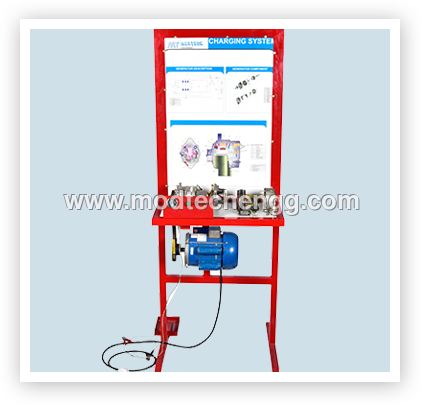

Price:
- 50
- 100
- 200
- 250
- 500
- 1000+
More Products in Instruction Boards/Training Platforms Category
INSTRUCTION BOARD FOR CENTRAL DOOR LOCKING AND ALARAM SYSTEM
Price 2000 INR
Minimum Order Quantity : 1 Unit
Size : Standard Classroom Board
Surface Finish : Powder Coated, UV Printed Panel
Color : Multicolor Panel with Printed Circuit Diagram
Material : Laminated Metal Sheet, Plastic Components, PCB Mounts
INSTRUCTION BOARD FOR ELECTRONIC FUEL INJECTION SYSTEM
Price 200000 INR
Minimum Order Quantity : 1 Unit
Size : Standard Laboratory Board Size
Surface Finish : Glossy Laminated, Scratch Resistant
Color : Multicolor (with colored circuit diagrams and labeling)
Material : Powder Coated Metal Board, Printed Synthetic Sheet
TRAINING PLATFORM FOR ABS BRAKE SYSTEM
Price 2000 INR
Minimum Order Quantity : 1 Unit
Size : Fullsize car ABS mockup
Surface Finish : Industrial powder coat, polished metal details
Color : Blue base with transparent acrylic section
Material : Powder coated steel, acrylic panel, stainless fasteners
REVERSE CAMERA AND PARKING ASSIST SYSTEM
Price 2000 INR
Minimum Order Quantity : 1 , , Unit
Size : Standard/Universal Fit
Surface Finish : Matte Antiglare Finish
Color : Black (Standard)
Material : Highgrade Plastic & Metal (for camera housing)

 Send Inquiry


 Send Inquiry
 Send SMS